
If you are just getting started with Arduino, one of the first things you’ll come across is analog inputs and PWM outputs. Many beginners often confuse ADC (Analog-to-Digital Converter) with DAC (Digital-to-Analog Converter), especially when working with the Arduino Uno.
In this article, we’ll explain how ADC and DAC work, which pins are used, and how you can use them in your own Arduino projects.
What is an ADC?
ADC stands for Analog-to-Digital Converter.
An ADC converts a continuously varying analog voltage into a digital number that the microcontroller can process.
Imagine turning a potentiometer. The voltage changes smoothly from 0V to 5V. Since the Arduino’s microcontroller understands only digital values, it converts this voltage into a number.
On the Arduino Uno, the ADC has 10-bit resolution, meaning it can represent:
- 0V = 0
- 5V = 1023
This gives a total of 1024 different levels.
The conversion formula is:
Digital Value = (Input Voltage ÷ Reference Voltage) × 1023
For example:
- 1V ≈ 205
- 2.5V ≈ 512
- 5V = 1023
Arduino Uno ADC Pins
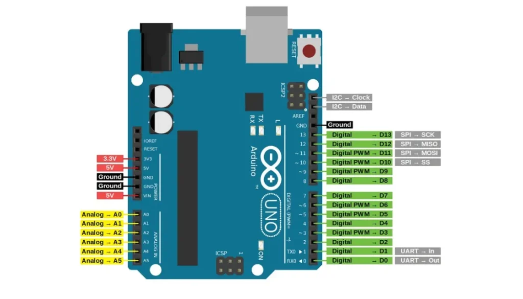
The Arduino Uno has six analog input pins:
- A0
- A1
- A2
- A3
- A4
- A5
These pins are connected to the ATmega328P’s internal ADC.
They can measure voltages between 0V and 5V (or another reference voltage if configured).
Typical sensors connected to ADC pins include:
- Potentiometers
- Temperature sensors
- Light sensors (LDRs)
- Gas sensors
- Pressure sensors
- Joysticks
- Battery voltage monitors
Reading an Analog Input
Reading an analog voltage is very simple.
//int sensorValue;
//void setup() {
//Serial.begin(9600);
}
//void loop() {
//sensorValue = analogRead(A0);
//Serial.println(sensorValue);
//delay(100);
}
If the input voltage on A0 is:
- 0V → 0
- 2.5V → about 512
- 5V → 1023
ADC Resolution
The Arduino Uno uses a 10-bit ADC.
| Resolution | Number of Levels |
|---|---|
| 8-bit | 256 |
| 10-bit (Arduino Uno) | 1024 |
| 12-bit | 4096 |
| 16-bit | 65,536 |
Higher resolution allows smaller voltage changes to be detected.
ADC Conversion Time
The Arduino Uno typically requires around 100 microseconds for one analog conversion.
This allows approximately 9,000 to 10,000 samples per second, making it suitable for many sensor applications.
What is a DAC?
DAC stands for Digital-to-Analog Converter.
A DAC performs the opposite function of an ADC.
It converts a digital value into a corresponding analog voltage.
DACs are commonly used for:
- Audio generation
- Signal generators
- Motor control
- Variable power supplies
- Analog instrumentation
Does Arduino Uno Have a DAC?
The answer is:
No.
The Arduino Uno does not contain a true hardware DAC.
This is one of the most common misconceptions among beginners.
Why Does Arduino Have PWM Pins?
The Arduino Uno includes six PWM pins:
- D3
- D5
- D6
- D9
- D10
- D11
These are often mistaken for DAC outputs.
PWM stands for Pulse Width Modulation.
Instead of producing a real analog voltage, PWM rapidly switches the output between HIGH (5V) and LOW (0V). By changing the duty cycle, the average voltage changes.
For example:
| PWM Value | Duty Cycle | Average Voltage |
|---|---|---|
| 0 | 0% | 0V |
| 64 | 25% | ≈1.25V |
| 128 | 50% | ≈2.5V |
| 192 | 75% | ≈3.75V |
| 255 | 100% | ≈5V |
Using PWM as a DAC
Although PWM is not a true analog signal, adding a simple RC low-pass filter can smooth the pulses into a voltage that behaves much like an analog output for many applications.
Example:
//void setup() {
}
}
//void loop()
 {
  analogWrite(9, 128);   // 50% duty cycle
}
analogWrite(9, 128); // 50% duty cycle
}
Connecting a resistor and capacitor after the PWM pin creates a smoother output voltage.
Applications of ADC
The Arduino’s ADC is used in countless projects, including:
- Reading sensor values
- Battery monitoring
- Solar energy systems
- Industrial automation
- Data logging
- Electronic instruments
- Oscilloscopes
- Weather stations
- Robotics
Applications of PWM (DAC Replacement)
PWM outputs can be used for:
- LED brightness control
- DC motor speed control
- Servo control
- Audio tone generation
- Fan speed regulation
- Simulated analog voltage
- Power converters
Arduino Boards with Real DAC
Unlike the Arduino Uno, some Arduino boards include true DAC hardware.
Examples include:
- Arduino Due (2 DAC outputs)
- Arduino Zero (1 DAC output)
- MKR series (selected models)
- Nano 33 IoT (PWM only, no true DAC)
If your project requires accurate analog voltage generation, choose a board with a built-in DAC or use an external DAC IC such as the MCP4725.
ADC vs DAC
| Feature | ADC | DAC |
|---|---|---|
| Full Name | Analog-to-Digital Converter | Digital-to-Analog Converter |
| Function | Converts voltage to numbers | Converts numbers to voltage |
| Direction | Analog → Digital | Digital → Analog |
| Arduino Uno | Yes | No |
| Resolution | 10-bit | Not available |
| Pins | A0–A5 | None |
| Alternative | — | PWM (D3, D5, D6, D9, D10, D11) |
Practical Example
Suppose you’re building a simple electronic thermometer.
- A temperature sensor outputs an analog voltage.
- The Arduino reads this voltage using the ADC on pin A0.
- The microcontroller calculates the temperature.
- The result is displayed on an LCD or OLED display.
Similarly, if you want to dim an LED, you can use PWM with analogWrite() to adjust its brightness by varying the duty cycle.
Conclusion
Understanding the difference between ADC and DAC is essential for every Arduino beginner. The Arduino Uno features a built-in 10-bit ADC on pins A0 to A5, making it easy to read analog sensors and voltages. While it does not include a true DAC, its PWM-capable digital pins can simulate analog outputs for many practical applications.
Whether you’re designing a weather station, building an oscilloscope, controlling motors, or creating automation projects, mastering ADC and PWM will help you make the most of your Arduino Uno and build more capable embedded systems.