How Avr works in a generator ?
When the engine rotates the generator, the rotor produces an AC voltage in the excitation winding. This AC voltage is converted into DC using a rectifier and capacitor.
The AVR continuously checks the output voltage of the generator. If the voltage is low, the AVR turns ON the transistor, allowing more current to flow into the field winding, which increases the output voltage.
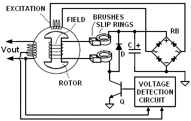
If the voltage becomes too high, the AVR turns the transistor OFF. Even when the transistor is OFF, the field current does not stop suddenly; it safely flows through a diode, preventing damage to components.
By rapidly switching the transistor ON and OFF (duty cycle control), the AVR maintains a stable output voltage.
Some generators use a small permanent magnet in the rotor to ensure that a minimum voltage is always available for excitation
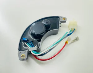
A standard 4-wire universal AVR has:
Two sensing / supply wires (AC input)
Often marked: AC / ~ / S / Input
Connected to generator stator output
Provides power and voltage feedback to the AVR
Two field wires (DC output)
Often marked: F+ / F- / + / –
Connected to rotor field winding via slip rings
Never confuse sensing wires with field wires — this is the most common mistake.
Identify Generator Terminals
Before wiring, identify these on your generator:
A) Stator Output (AC)
Usually labeled:
L – N
R – S
220V / 110V output
Use a multimeter to confirm AC voltage when generator runs
B) Rotor Field Wires
Two wires coming from slip rings
Low resistance (typically 10–50 Ω)
These go directly to the AVR field output
Step 1: Power Off
Engine must be OFF
Remove and disconnect the old AVR completely
Step 2: Connect AC Sensing Wires
Connect the AVR AC input wires to generator output L and N
For 220V systems, connect across the full output
For dual-voltage generators, use the high-voltage terminals
Step 3: Connect Field Wires
Connect AVR F+ and F- to the rotor slip rings
Ensure tight and clean connections
Step 4: Set AVR Voltage Adjustment
Turn the AVR voltage adjustment potentiometer fully anticlockwise
This prevents over-voltage during first startup
Step 5: Start the Generator
Run the generator at rated speed (1500 or 1800 RPM)
Slowly rotate the AVR voltage adjustment clockwise
Stop when rated voltage appears (110V or 220V)
5. If Voltage Does Not Build Up
Check the following:
Reverse the F+ and F- connections
Increase engine speed
Check residual magnetism
Flash the field with 12V DC for 1 to 2 seconds
Verify AC voltage at the AVR input terminals
6. Common Wiring Mistakes
Connecting field wires to stator output
Supplying AVR from incorrect voltage tap
Running generator below rated RPM
Adjusting AVR before engine stabilizes
Using incorrect AVR voltage rating
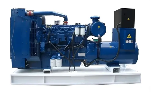
7. Typical Applications
Petrol and diesel generators
Brush-type alternators
Single-phase self-excited generators
Industrial and rental generator sets